

Click to open expanded view
1×N MEMS Optical Switch Module
Features
Mini Size
Fast Switch Speed
Low Insertion Loss & PDL
Wide Operating Wavelength Range
High Reliability & Stability
Applications
Network Monitor System
Remote Fiber Testing System
Module & System Integration
Instrumentation
Technical Parameters
Single Mode
|
Parameters Unit MEMS 1×N-SM |
|||
|
Working Wavelength |
nm |
O/C/L/L+ band |
|
|
Testing Wavelength |
nm |
1310/1550/1625/1650 |
|
|
Insertion Loss |
dB |
@CWL Single-band ≤0.8 (N≤8) ≤1.0 (8 ≤1.3 (16 ≤1.5 (32 ≤2.0 (64 ≤2.2 (144 |
@CWL Dual-band ≤1.0 (N≤8) ≤1.2 (8 ≤1.5 (16 ≤1.7 (32 ≤2.2 (64 ≤2.4 (144 |
|
WDL |
dB |
≤0.3 (N≤64) ≤0.4 (64 ≤0.5 (144 |
|
|
PDL |
dB |
≤0.15 |
|
|
Return Loss |
dB |
≥45 |
|
|
Crosstalk |
dB |
≥50 |
|
|
Repeatability |
dB |
≤±0.05 |
|
|
Switching Time |
ms |
≤15 |
|
|
Durability |
times |
≥109 |
|
|
Input Optical Power |
mW |
≤500 |
|
|
Operating Voltage |
V |
DC 5V±10% |
|
|
Operating Current |
mA |
≤50 (N≤16) ≤250 (16 ≤350 (64 ≤500 (144 |
|
|
Operating Temp. |
°C |
-20 ~ +85 |
|
|
Storage Temp. |
°C |
-40 ~ +85 |
|
|
Dimension (L×W×H) |
mm |
M1: 34×24×11 ±0.2 (N≤64, Bare Fiber) M2: 60×24×11 ±0.2 (N≤16, Loose Tube) M3: 90×55×12 ±0.2 (16 M4: 100×100×12 ±0.2 (64 M5: 110×141×12 ±0.2 (144 |
|
1. Excluding connector.
2. Within operating temperature and all SOP.
3. WDL is measured in a ±20nm range at 23°C。
Multi-Mode
|
Parameters Unit MEMS 1×N-MM |
|||
|
Working Wavelength |
nm |
850±30, 1310±30 |
|
|
Testing Wavelength |
nm |
850/1310 |
|
|
Insertion Loss |
dB |
@CWL Single-band ≤0.8 (N≤12) ≤1.0 (12 ≤1.8 (16 |
@CWL Dual-band ≤1.0 (N≤12) ≤1.2 (12 ≤2.0 (16 |
|
WDL |
dB |
≤0.3 (N≤16) ≤0.4 (16 |
|
|
PDL |
dB |
≤0.2 |
|
|
Return Loss |
dB |
≥30 |
|
|
Crosstalk |
dB |
≥30 |
|
|
Repeatability |
dB |
≤±0.05 |
|
|
Switching Time |
ms |
≤15 |
|
|
Durability |
times |
≥109 |
|
|
Input Optical Power |
mW |
≤500 |
|
|
Operating Voltage |
V |
DC 5V±10% |
|
|
Operating Current |
mA |
≤50 (N≤16) ≤250 (16 ≤350 (64 |
|
|
Operating Temp. |
°C |
-20 ~ +85 |
|
|
Storage Temp. |
°C |
-40 ~ +85 |
|
|
Dimension (L×W×H) |
mm |
M1: 34×24×11 ±0.2 (N≤16, Bare Fiber) M2: 60×24×11 ±0.2 (N≤16, Loose Tube) M3: 90×55×12 ±0.2 (16 M4: 100×100×12 ±0.2 (64 |
|
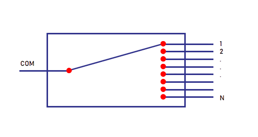
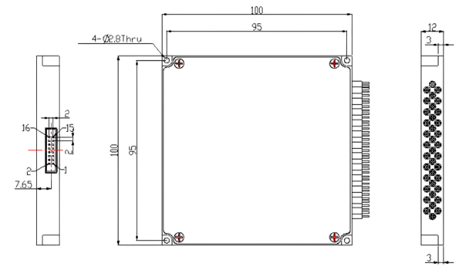
Optical Path Diagram
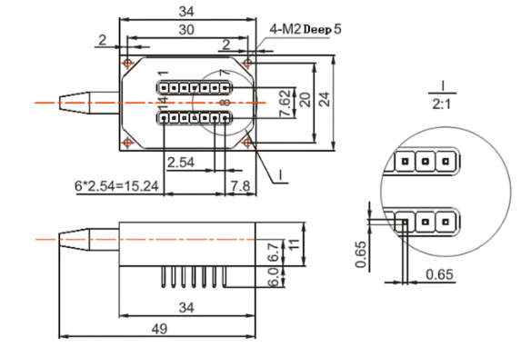
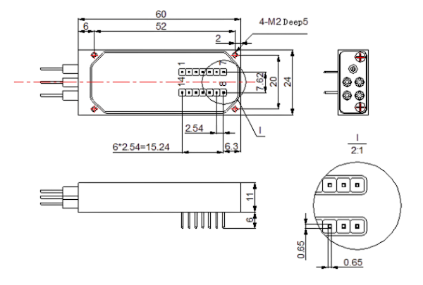
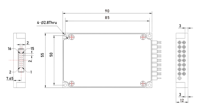
Dimension(mm)
М1: 34 × 24 × 11 mm
М2: 60 х 24 х 11 mm
M3: 90×55×12mm
М4: 100 х100 х12 mm
Ordering Information: HC-MEMS-1×N-A-B-C-D-E-F-G
|
N |
A |
B |
C |
D |
E |
F |
G |
|
Channels |
Mode |
Wavelength |
Dimension |
Fiber Type |
Fiber Diameter |
Fiber Length |
Connector |
|
1 ........
256 |
S: SingleMode
M: Multi-Mode |
85: 850nm
13:1310nm
14:1490 nm
15:1550 nm
162:1625 nm
165:1650 nm
13/15: 1310/1550 nm
X:other |
M1: 34×24×11
M2: 60×24×11
M3: 90×55×12
M4: 100×100×12
M5: 110×141×12
X:other |
5:50/125
6:62.5/125
9:9/125
X:other |
25:Φ0.25mm
90:Φ0.9mm
X:other |
05:0.5m
10:1.0m
15:1.5m
X:other |
00:None
FP:FCU/PC
FA:FC/APC
SP:SC/UPC
SA:SC/APC
LP:LC/UPC
LA:LC/APC
MP:MPO
X: other |
If you need more support , Please contact us.
