
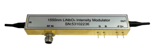
Click to open expanded view
LiNbO3 intensity modulator
The analog intensity modulators offered by HC Optical combine high linearity with low drive voltage and small package size, with bandwidths ranging from 20 GHz (AM20) to a wider 40 GHz (AM40). Due to the increasing bandwidth requirements in analog fiber transmission applications, LiNbO3(lithium niobate) intensity modulators for high-bandwidth analog applications from HC Optical can meet higher-end requirements and provide more suitable solutions. Our experience also allows us to provide customized services to our customers.
Main characteristics
• Integrated polarizer
• Integrated photodiodes
• Low optical insertion loss
• X-cut lithium niobate crystal
• Titanium diffused waveguides
• Operating bandwidths up to 60 GHz
• Low drive voltage compatible with commercially available drives
Application
• Instrumentation
• Digital transmission
• Analog transmission
• Delayed telemetry system
• High frequency fiber connectivity
Absolute maximum rating
|
Parameter |
Condition |
Minimum value |
Maximum value |
Unit |
|
Maximum RF input power (electrical) |
RF port AC-coupled AC |
- |
25 |
dBm |
|
Maximum input optical power (optical) |
Continuous power CW |
- |
100 |
mW |
|
Enclosure operating temperature |
- |
0 |
+ 70 |
°C |
|
Storage temperature |
- |
- 40 |
+ 85 |
°C |
|
Rate of change of maximum operating temperature |
- |
- |
1 |
° C/min |
|
Operating humidity |
- |
5 |
85 |
% |
|
Pin Soldering Temperature |
- |
- |
250 |
°C |
|
Maximum lead bonding time |
- |
- |
10 |
s |
Technical parameters
|
Parameter |
Condition |
Value (AM20) |
Value (AM40) |
Unit |
|
Optical parameters |
|
|
||
|
Operating wavelength range |
- |
1525 - 1615 |
1525 - 1615 |
nm |
|
Insertion Loss, IL |
No connector With connector |
(3.5 typical) < 4.5 (4.0 typical) < 5.0 |
(4.0 typical) < 5.0 (4.5 typical) < 5.5 |
dB |
|
Return Loss, RL |
No connector |
> 45 |
> 45 |
dB |
|
Extinction Ratio, ER |
- |
> 20 (23 typical) |
> 20 (23 typical) |
dB |
|
Electrical parameters |
|
|
||
|
S21 electro-optic bandwidth |
-3dBe |
> 20 (23 typical) |
> 30 (33 typical) |
GHz |
|
S11 return loss |
40 MHz – 20 GHz 20 GHz – 35 GHz |
< -10 (-12 typical) - |
< -10 (-12 typical) < -8 (-10 typical) |
dB |
|
RF Vπ voltage |
@ 1 kHz |
< 5.0 (4.5 typical) |
< 5.2 (4.7 typical) |
V |
|
RF Vπ voltage |
@ 20 GHz |
6.0 |
6.0 |
V |
|
RF input impedance |
- |
50 |
- |
Ω |
|
Bias Vπ voltage |
@ 1 kHz |
< 5.5 (5.0 typical) |
< 5.5 (5.0 typical) |
V |
|
Bias input impedance |
@ DC |
1 |
1 |
MΩ |
|
Photodiode responsivity |
- |
> 1x10⁻³ |
> 1x10⁻³ |
mA/W |
|
The linearity |
- |
± 10% |
± 10% |
|
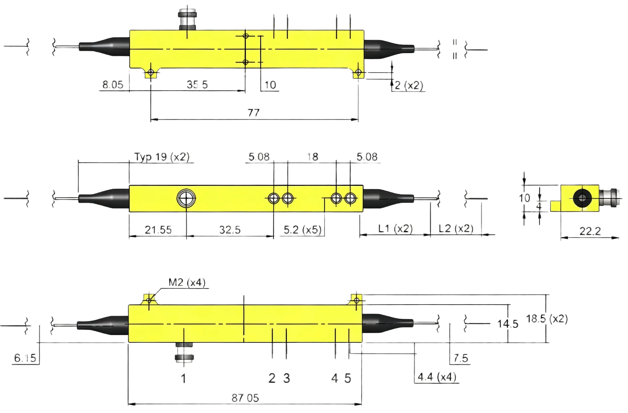
Package appearance
If you need more Information , Please contact us .

