

Click to open expanded view
MXN MEMS Matrix Optical Switch Equipment
Product description
The matrix optical switch device is a kind of OXC optical path control device, which plays the role of controlling the optical path and switching the optical path. And play an important role in optical communication application. It is mainly used in multi-channel optical monitoring, LAN multi-light source/detector automatic switching and optical sensing multi-point dynamic monitoring system in optical transmission system, optical fiber, optical device, network and field engineering optical cable test in optical test system, and optical fiber, optical device, network and field engineering optical cable test in optical test system. Optical device assembly and adjustment.
Transparent transmission: Due to its exchange at the optical layer, it is completely transparent to the signal's rate, format, and protocol. Whether it's 10G, 100G, 400G, or the 800G signals, and whether it's SDH, OTN, or Ethernet protocols, OCS can handle them all equally. This is one of its core advantages.
Product features
The insertion loss is small
High stability and reliability
The switching speed is fast
Light path switching can be set by serial port command
Application
Optical fiber sensing
System monitoring
Metropolitan Area Network
Multi-channel optical monitoring
Remote optical fiber monitoring system
Laboratory research and development
Technical Parameters
|
Model |
OXC-MⅹN-SM |
OXC-MⅹN-MM |
|
Fiber type |
SM(9/125um) |
MM(50/125um or 62.5/125um) |
|
Operating wavelength |
1260~1650nm |
820~880nm |
|
Test wavelength |
1310/1550/1625/1650 |
850 |
|
Insertion loss |
≤2.0 dB @ M+N≤16 ≤2.5 dB @ M+N≤32 ≤3.0 dB @ M+N≤64 ≤3.5 dB @ M+N≤128 |
≤2.0 dB @ M+N≤16 ≤2.5 dB @ M≤16,N≤16 ≤4.5 dB @ M≤32,N≤32 |
|
Return loss |
≥45 dB |
≥30 dB |
|
Cross talk |
≥50 dB |
≥30 dB |
|
Repeatability |
≤±0.1dB |
|
|
Switching time |
≤15 (M≤16, N≤16) ≤50(M≤64, N≤64) |
|
|
Number of switches |
≥ 10 9 times |
|
|
Optical interface type |
LC/UPC (customizable) |
|
|
Input optical power |
≤500 mW |
|
|
Monitoring port |
RJ45、RS-232 |
|
|
Working power supply |
AC: 85 ~ 264 V (50/60Hz) or DC: 36 ~ 72 V |
|
|
Operating temperature |
-5 ~ + 70℃ |
|
|
Storage temperature |
-40 ~ + 80°C |
|
|
Chassis Dimensions 19-inch standard 1U rack (483 × 500 × 44mm) 19-inch standard 2 U rack (483 × 500 × 89mm) 19-inch standard 4 U rack (483 × 500 × 176mm) |
LC flange layout 1U:M+N≤64 2U: M+N≤128 |
LC flange layout 1U:M+N≤32 2U: M+N≤64 |
|
FC flange layout 1U:M+N≤16 2U: M+N≤32 4U: M+N≤64 |
FC flange layout 1U:M+N≤16 2U: M+N≤32 4U: M+N≤64 |
|
Note:
1. All parameters are tested at room temperature.
2. The above is the adaptive chassis size of LC and FC flange layout, and the chassis mechanism of other flanges shall be confirmed separately.
3. The above is the insertion loss value without power monitoring and with power monitoring, increasing 0.5dB for each channel.
Schematic description of the structure
Front panel description:
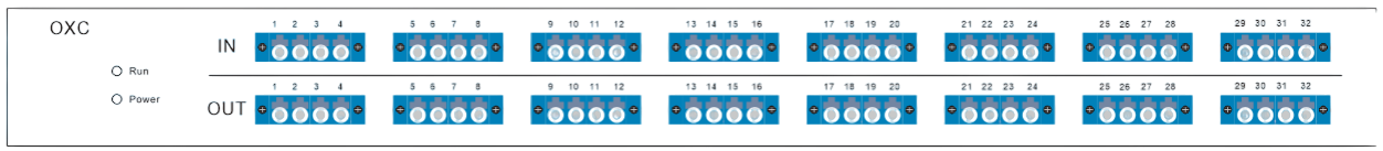
1U
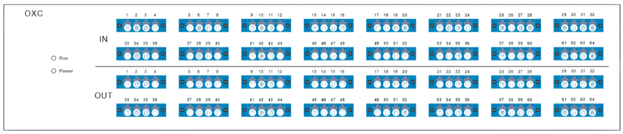
2U
(1) Indicator light: Power indicator. If the light is on, it means the power supply is normal. Run indicates the operation of the device, which flashes once every 1 second of normal operation.
(2) Optical interface: In 1-64 is the input port, and Out 1-64 is the output port.
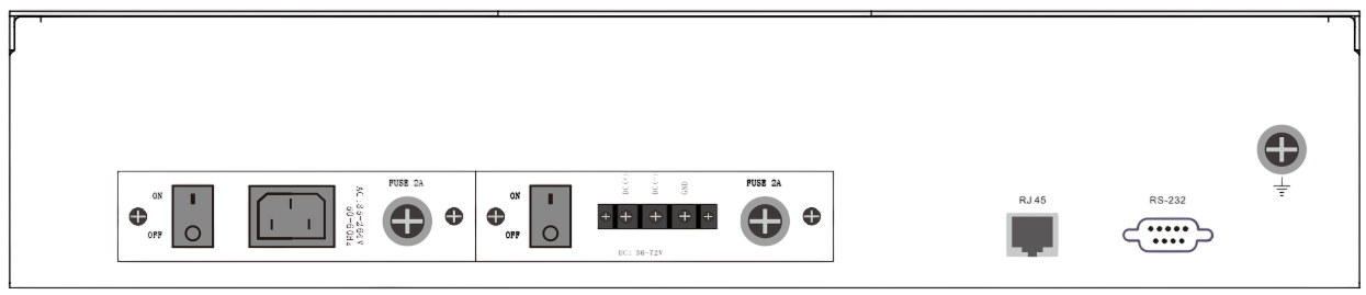
Back panel description:

1U
2U
(1) AC, DC power interface: equipment working power input interface.
(2) RJ45 Ethernet interface and RS-232 serial port: communication interface for equipment monitoring data information.
(3) Wiring post: external grounding post.
If you need more support , Please contact us .
