

Click to open expanded view

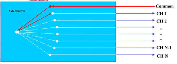
1×256 MEMS optical switch module
Features
Mini Size
Fast Switch Speed
Low Insertion Loss & PDL
High Reliability & Stability
Wide Operating Wavelength Range
Application
Instrumentation
Network Monitor System
Remote Fiber Testing System
Module & System Integration
Optical Path Diagram
Technical Parameters
|
Type |
MEMS-1X256-S-165-M5-9-90-05-MP |
|
Fiber type |
SM |
|
Working Wavelength |
1260-1650nm |
|
Insert Loss 1 |
≤2.8dB |
|
PDL |
≤0.15dB |
|
Return Loss |
≥45 dB |
|
Channel Crosstalk |
≥50 dB |
|
Repeatability |
≤±0.05dB |
|
Switching time |
≤15ms |
|
Durability |
≥109 |
|
Connector |
COM port LC / APC, other ports MPO / APC (24 core male) |
|
Pigtail Length |
0.5m |
|
Input Optical Power |
≤500 mW |
|
Power supply |
DC5V±10%, 500mA |
|
Operating Temperature |
-5 ~ 70 °C |
|
Store Temperature |
-40 ~ 85 °C |
|
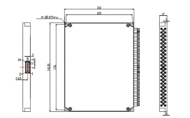
Module size |
110(L) x 141(W) x 12(H) ±0.2mm |
Note: 1. All parameters are tested at room temperature.
Module size (mm)
M5:
Pin definition
|
Pin# |
Signal name |
Type |
Description |
|
1 |
D0 |
Input |
Data bit D0(low) |
|
2 |
D5 |
Input |
Data bit D5 |
|
3 |
VCC |
Power |
Power supply,DC 5V,1.0A |
|
4 |
D7 |
Input |
Data bit D7(high) |
|
5 |
D6 |
Input |
Data bit D6 |
|
6 |
GND |
Power |
GND |
|
7 |
D4 |
Input |
Data bit D4 |
|
8 |
D1 |
Input |
Data bit D1 |
|
9 |
TXD |
Output |
RS232 TX(TTL) |
|
10 |
RXD |
Input |
RS232 RX(TTL) |
|
11 |
D2 |
Input |
Data bit D2 |
|
12 |
D3 |
Input |
Data bit D3 |
|
13 |
/BUSY |
Output |
Normally pulled low. While a module is busy, it will be pulled high. |
|
14 |
/ALARM |
Output |
Normally pulled low. While a module logged alarms, it will be pulled high. |
|
15 |
/STROBE |
Input |
Falling edge active to synchronize command execution. |
|
16 |
/RESET |
Input |
Low reset to channel 0, high data bit effective. |
Note: The module electrical interface uses MOMOLEX's 87833-1620 and the customer connector is recommended to use MOMOLEX's 87568-1694.
The Data Bit Switching Logic Table
|
/RESET |
D7 |
D6 |
D5 |
D4 |
D3 |
D2 |
D1 |
D0 |
Channel |
|
0 |
X |
X |
X |
X |
X |
X |
X |
X |
0 |
|
1
|
0 |
0 |
0 |
0 |
0 |
0 |
0 |
0 |
1 |
|
0 |
0 |
0 |
0 |
0 |
0 |
0 |
1 |
2 |
|
|
0 |
0 |
0 |
0 |
0 |
0 |
1 |
0 |
3 |
|
|
0 |
0 |
0 |
0 |
0 |
0 |
1 |
1 |
4 |
|
|
… |
… |
… |
… |
… |
… |
… |
… |
… |
|
|
1 |
1 |
1 |
1 |
1 |
1 |
1 |
1 |
256 |
Fiber Length

Contains Boot and Connector length
Factory Default Configuration
|
Project |
Factory default configuration |
Note |
|
Serial port rate |
115200 |
8 bit data bit,1 bit stop bit, no parity. |
|
Working mode |
The data bit controls the switch |
|
|
Working channel |
When the data bit control switches, the working channel is determined by the data bit. When UART control is switched , The working channel is channel 1; |
When UART control is switched, The light path state at the time of configuration saving is maintained after the module is powered off and then powered on. |
If you need more support , Please contact us.
