
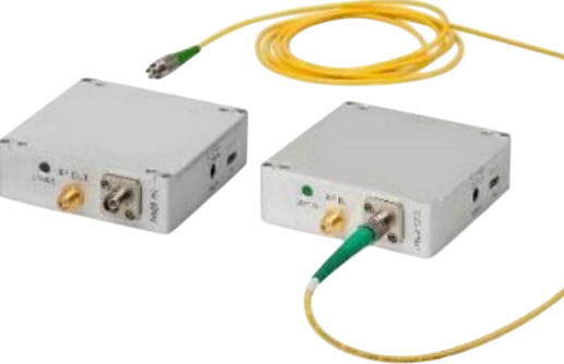
Click to open expanded view
12GHz Microwave Photonic RFoF Module
Key Features
Ø High P1dB input power
Ø High SFDR: 111dB/Hz²ᐟ³
Ø Excellent phase linearity performance
Ø Outstanding phase noise performance
Ø Laser wavelength: 1550nm
Ø Low power consumption
Ø Frequency range: 0.1~12GHz (0.02~12GHz optional)
Configurations
Ø Standard model (single channel)
Ø 1U general chassis (8 units)
Ø 1U detachable front panel chassis (4 units)
Ø Outdoor enclosure (4/8 units)
Applications
Ø Radio telescopes
Ø Electronic warfare
Ø Romote antennas
Ø Distributed antennas
Ø Satellite communications
Ø Wireless communications:
Ø Long distance RF transmission over fiber optic
Optional Customizations
· Multi-link phase matching
· Extended low-frequency coverage
· Dense Wavelength Division Multiplexing (DWDM)
· Integrated pre-amplifier / post-amplifier with configurable gain, P1dB, noise figure (NF), etc.
The compact Ultra series microwave photonic modules support long-distance transmission of broadband RF signals. The transmitter unit modulates broadband RF signals onto an optical beam for transmission over fiber to the receiver unit, which recovers the modulated optical signals back into RF signals. The single-mode fiber interconnecting the two units is generally supplied by the customer; fiber is only provided by our company as part of microwave photonic link assemblies for specific applications.
In general, transmission of multiple RF signals at varying power levels requires links with ultra-wide Spurious-Free Dynamic Range (SFDR). A high IP1dB value (1dB compression point input power) allows the microwave photonic modules to operate at nominal signal levels without additional attenuation. Integrating low-noise amplifiers within Ultra transmitter modules effectively optimizes noise figure performance. The high SFDR capability suits 5G testing, antenna testing, radar and altimeter system testing, and other scenarios. The wide dynamic range enables simultaneous transmission of signals with drastically different power levels (e.g., main lobe vs. side lobe signals, close-range vs. long-range target signals) while minimizing inter-signal interference. This also applies to DF/ELINT systems, which must concurrently process strong interfering signals and accompanying weak target signals.
The 12/18/20GHz Ultra series microwave photonic solutions deliver high SFDR performance of 111dB/Hz²ᐟ³. Thanks to elevated IP1dB specifications, the system can carry higher signal power levels without distortion, making it widely applicable in civil communications, remote antenna control, telemetry & telecommand, point-to-point communications, defense systems, satellite communications, and other fields.
RF Parameters (Full Tx-Rx Link Typical Specifications)
|
RF Parameter |
Unit |
Typical Value |
|
Frequency Range [1] |
GHz |
0.1~12 |
|
Gain [2,3] |
dB |
-29 |
|
Gain Flatness [4] |
dB |
±1.2 |
|
Input 1dB Compression Point [3] |
dBm |
24 |
|
Noise Figure [2,3] |
dB |
41 |
|
Spurious-Free Dynamic Range (Calculated) [3,5] |
dB/Hz²ᐟ³ |
111 |
|
Max RF Input Level (Non-Damaging) |
dBm |
21 |
|
Input/Output VSWR |
— |
2.0:1 |
|
Spurious Response [6] |
dBc |
≤-90 |
|
Phase Noise @10kHz Offset |
dBc/Hz |
≤-130 |
|
Input/Output Impedance |
Ohm |
50 |
Optical, Electrical & Environmental Specifications (Tx/Rx Modules)
|
Parameter |
Unit |
Typical Value |
|
Transmitter Photodiode Wavelength |
µm |
1.55 |
|
Receiver Photodiode Wavelength |
µm |
1.1~1.65 |
|
Operating Temperature |
°C |
-20~+70 |
|
Storage Temperature |
°C |
-40~+85 |
|
LED Status Indicator (Tx/Rx) |
— |
Blue/Green/Red |
|
Operating Voltage |
VDC |
5–12 |
|
Power Consumption – Tx Module [4] |
Watt |
0.95 |
|
Power Consumption – Rx Module [4] |
Watt |
0.25 |
Mechanical Specifications (Tx/Rx)
|
Parameter |
Unit |
Typical Value |
|
Overall Dimensions (Tx/Rx) [7] |
mm |
70 × 70 × 22 |
|
Unit Weight |
grams |
220 |
|
RF Input/Output Connector |
— |
SMA |
|
Fiber Optic Connector |
— |
FC/APC |
|
Power Connector |
— |
PIN 3.5 × 1.3 × 9 |
|
Data/Monitoring Connector [7] |
— |
USB-C |
Notes
[1] Extended low-frequency option available: 0.02~12GHz.
[2] Excludes fiber loss from customer cabling.
[3] Tested at 10GHz; gain, P1dB and noise figure values are typical. Typical values for units with integrated pre/post amplifiers are listed in the table below.
[4] Each optional pre/post amplifier adds approximately ±1dB gain ripple and 1.8W module power consumption.
[5] In-band harmonics excluded; SFDR (calculated) ≈ (2/3) × [(IP1dB+10) + 174-NF] dB/Hz²ᐟ³.
[6] Tested at 1GHz with input power set to IP1dBc – 3dB.
[7] Overall dimensions for integrated indoor and outdoor enclosures are listed in Table following.
[8] Contact sales staff to download USB interface control software.
Ultra Series 12GHz Microwave Photonic Module Options
|
Parameter |
Unit |
Ultra 12GHz Transceiver (No Integrated Amplifier) |
Ultra 12GHz Transceiver (Integrated Pre-Amp) |
Ultra 12GHz Transceiver (Integrated Post-Amp) |
Ultra 12GHz Transceiver (Integrated Pre+Post Amplifier) |
|
Model Number |
— |
RFoF-12GHz-N0-Ultra |
RFoF-12GHz-A0-Ultra |
RFoF-12GHz-A1-Ultra-P |
RFoF-12GHz-A2-Ultra |
|
Gain* |
dB |
-29 |
-13 |
-13 |
4 |
|
Input P1dB* |
dBm |
24 |
7 |
24 |
7 |
|
Noise Figure* |
dB |
41 |
25 |
41 |
26 |
|
SFDR* |
dBc/Hz²ᐟ³ |
111 |
110 |
110 |
110 |
*Tested at 10GHz. For modules integrated into unified indoor/outdoor enclosures, NF and P1dB degrade by ~2dB, and gain reduces by ~2dB.
If you need more support , Please contact us .

