

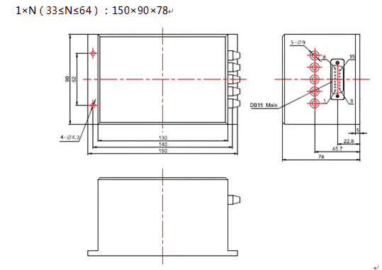
Click to open expanded view
1×N Mechanical Multiplexing Optical Switch
Features
Low Crosstalk
Low Insertion Loss
Modularized Design
Parallel Interface (TTL)
Wide Wavelength Range
High Stability and Reliability
Applications
Configuration OADM
Optical Fiber Sensing
Multiple light monitoring
Laboratory development
Metropolitan area network
Remote optical fiber monitoring system
Technical Parameters
|
Model |
HC- FSW - 1×N |
||
|
Wavelength Range nm |
800~1100(MM) |
1400~1700(MM) |
1250~1650(SM) |
|
Test Wavelength nm |
850/980 |
1550 |
1310/1490/1550/1625 |
|
Insertion Loss dB |
Typ:0.6 Max:1.0 |
Typ:0.6 Max:1.0 |
Typ:0.8 Max:1.3 |
|
Return Loss dB |
SM≥50、MM≥30 |
||
|
Crosstalk dB |
≥70 |
||
|
Polarization-Dependent Loss dB |
≤0.05 |
||
|
Wavelength-Dependent Loss dB |
≤0.25 |
||
|
Temperature-Dependent Loss dB |
≤0.25 |
||
|
Repeatability dB |
≤±0.02 |
||
|
Working voltage V |
+5 (DC) |
||
|
The service life of the times |
≥107 |
||
|
Switch time ms |
≤10( Adjacent channel switching ) |
||
|
Optical Power mW |
≤500 |
||
|
Operating Temperature ℃ |
-20~+70 |
||
|
Storage Temperature ℃ |
-40~+85 |
||
Attention: The above is the index without connector;
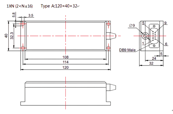
Pin Definition
DB9(TTL level)
|
Pin Number |
Signal direction、type (In/Out/Power) |
Pin definition |
Function Description |
|
1 |
In |
D0 |
Data bit D3~D0 are a binary number,D3 is high, D0 is low.Up to 16 optical switches can be controlled with 4 data bits. Where 0000b = channel 1; 1111b= channel 16. When used, data is sent based on the actual number of channels of the optical switch. |
|
2 |
In |
D1 |
|
|
3 |
In |
D2 |
|
|
4 |
In |
D3 |
|
|
5 |
In |
/Reset |
Low level reset to channel 0, high level data bit available |
|
6 |
Out |
/Ready |
Low level ready to reset or receive data |
|
7 |
Out |
Error |
High level indicates that the optical module is operating incorrectly |
|
8 |
Power |
GND |
Ground wire |
|
9 |
Power |
DC 5V |
DC 5V,1.0A Working power supply |
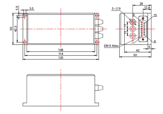
DB15(TTL level):
|
Pin Number |
Signal direction、type (In/Out/Power) |
Pin definition |
Function Description |
|
2 |
In |
D0 |
Where, 000000b = channel 1;111111 b = channel 64 . Data should be sent according to the actual optical path of the optical switch. |
|
3 |
In |
D1 |
|
|
4 |
In |
D2 |
|
|
5 |
In |
D3 |
|
|
6 |
In |
D4 |
|
|
10 |
In |
D5 |
|
|
11 |
In |
/Reset |
Low level reset, high level data bit effective |
|
7 |
Out |
/Ready |
Low level ready to reset or receive data |
|
8 |
Out |
Error |
A high level indicates an error has occurred |
|
15 |
Power |
5V |
Digital circuit power supply |
|
12 |
Power |
5V |
The motor power |
|
1,9 |
Power |
Ground |
Common ground |
|
13,14 |
Not connected |
||
Dimensions L×W×H (mm)
1XN (2≤16) Type B: 135×60×35

1×N(17≤N≤32) Type A:120×50×50

![]()
Order information HC-FSW-1×N-A-B-C-D-E-F
|
N |
A |
B |
C |
D |
E |
|
Channel Number |
Optical Fiber Specification |
Working Wavelength |
Optical Fiber Diameter |
Fiber Length (Include connector) |
Connector |
|
1 ~ 128 |
SM: SM, 9/125 M5: MM, 50/125 M6: MM,62.5/125 |
850: 850nm 1310: 1310nm 1550: 1550nm 31/55:1310/1550nm X: other |
90: 900um 20: 2.0mm 30: 3.0mm X: Others |
05: 0.5m±5cm 10: 1.0m±5cm 15: 1.5m±5cm X: Others |
OO:None FP: FC/PC FA: FC/APC SP: SC/PC SA: SC/APC LP: LC/PC LA: LC/APC X: Others |
|
F(Size code) |
Applicable models |
Overall dimensions(mm) |
|
1 |
1XN (2 |
Type A:120×40×32 |
|
2 |
1XN (2 |
Type B: 135×60×35 |
|
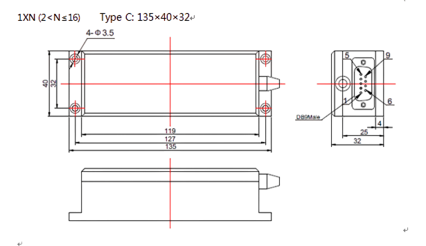
3 |
1XN (2 |
Type C: 135×40×32 |
|
4 |
1×N(17≤N≤32) |
Type A:120×50×50 |
|
5 |
1×N(17≤N≤32) |
Type B: 114x110x32 |
|
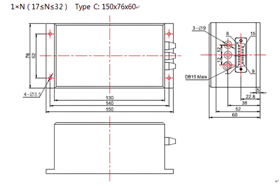
6 |
1×N(17≤N≤32) |
Type C: 150x76x60 |
|
7 |
1×N(33≤N≤64) |
150×90×78 |
|
8 |
1×N(65≤N≤128) |
172×150×78 |
If you need more support , Please contact us.
