

Click to open expanded view
D2×2 Bypass Optical Switch
Features
Low Crosstalk
Low Insertion Loss
Compact Structure
Fast Switching Speed
Wide Wavelength Range
Applications
Network Monitoring
Optical Protection System
Test and measurement System
Passive Optical Network (PON)
Technical Specification
|
Parameters |
Unit |
HC-OSW-D2×2 |
|
Operating Wavelength |
nm |
MM:850±40 |
|
Test Wavelength |
nm |
850 |
|
Insertion Loss |
dB |
≤1.0(Typical:0.8) |
|
WDL |
dB |
≤0.25 |
|
TDL |
dB |
≤0.4 |
|
PDL |
dB |
≤0.05 |
|
Return Loss |
dB |
≥30 |
|
Crosstalk |
dB |
≥35 |
|
Repeatability |
dB |
≤±0.02 |
|
Switching Speed |
ms |
≤8 |
|
Switching Times |
times |
≥10 million |
|
Operating Voltage |
V |
3.0 or 5.0 |
|
Power Handling |
mw |
≤500 |
|
Operating Temperature |
℃ |
-5~+70 |
|
Storage Temperature |
℃ |
-40~+85 |
|
Operating Humidity |
RH% |
5~95 |
|
Size |
mm |
L27xW12.6xH8.5(±0.2) |
|
Note:1.All parameters are tested under room-temperature operating conditions. |
||
|
2.All parameters exclude connector insertion loss; each pair of connectors adds 0.3 dB loss. |
||
Pin Definition
|
Type |
Status |
Optical Path |
Electronic Control Drive |
Status Indicator |
||||||
|
D2x2 |
|
|
Pin 1 |
Pin 5 |
Pin 6 |
Pin 10 |
Pin 2-3 |
Pin 3-4 |
Pin 7-8 |
Pin 8-9 |
|
Latch |
A |
P1- P2, P1‵-P2‵ |
- |
- |
GND |
V+ |
Close |
Open |
Open |
Close |
|
P3- P4, P3‵-P4‵ |
||||||||||
|
B |
P1-P4,P2-P3 |
V+ |
GND |
- |
- |
Open |
Close |
Close |
Open |
|
|
P1‵-P4‵,P2‵-P3‵ |
||||||||||
|
Non- Latch |
A |
P1- P2, P1‵-P2‵ |
- |
- |
- |
- |
Close |
Open |
Open |
Close |
|
P3- P4, P3‵-P4‵ |
||||||||||
|
B |
P1-P4,P2-P3 |
V+ |
- |
- |
GND |
Open |
Close |
Close |
Open |
|
|
P1‵-P4‵,P2‵-P3‵ |
||||||||||
Electrical Control Specifications
|
Type |
Voltage |
Current |
Resistance |
|
5V Latching |
4.5~5.5V |
36~44mA |
125Ω |
|
5V Non-Latching |
4.5~5.5V |
26~32mA |
175Ω |
|
3V Latching |
2.7~3.3V |
54~66mA |
50Ω |
|
3V Non-Latching |
2.7~3.3V |
39~47mA |
70Ω |
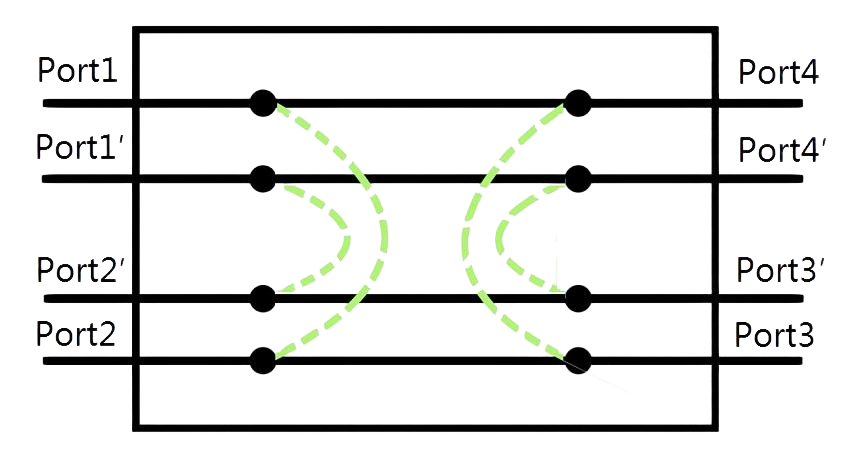
Optical Path Diagram
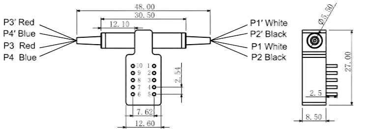
Dimension(mm)
Ordering Information:HC-OSW-D2×2-A-B-C-D-E-F
|
A |
B |
C |
D |
E |
F |
|
Test Wavelength |
Latch mode |
Fiber Type |
Fiber Diameter |
Fiber Length |
Connector Type |
|
850=850nm |
3L=Latching |
M1=MM 50/125 |
025=Φ0.25mm |
05=0.5m |
00=None |
|
|
3N=Non-Latching |
M2=MM 62.5/125 |
09=Φ0.9mm |
10=1.0m |
FP=FC/UPC |
|
|
5L=Latching |
X=Others |
X=Others |
15=1.5m |
FA=FC/APC |
|
|
5N=Non-Latching |
|
|
X=Others |
SP=SC/UPC |
|
|
|
|
|
|
SA=SC/APC |
|
|
|
|
|
|
LP=LC/UPC |
|
|
|
|
|
|
LA=LC/APC |
|
|
|
|
|
|
X=Others |
If you need more support , Please contact us .

