
Why AWG Is the Preferred Choice for Next-Generation Optical Multiplexing
Updated at Aug 27th 2026 Views 523
1. Introduction
As global data traffic continues its explosive growth—driven by AI computing clusters, cloud services, and 5G deployment—optical networks face unprecedented demands for bandwidth, speed, and cost efficiency. At the heart of this optical revolution lies a critical passive component: the Arrayed Waveguide Grating (AWG) .
AWG is a planar lightwave circuit (PLC) device fabricated on a chip substrate using semiconductor manufacturing techniques. It serves as the cornerstone of dense wavelength-division multiplexing (DWDM) systems, enabling the scalable multiplexing, demultiplexing, and routing of multiple optical wavelengths on a single fiber.
HC Optical, a leading provider of optical communication solutions, offers a comprehensive range of AWG products including 50GHz 80-channel athermal AWG modules in 1U rackmount form factors. These high-density DWDM multiplexing and demultiplexing solutions are designed for next-generation optical networks, delivering low insertion loss, high channel isolation, wide passband, and exceptional thermal stability without requiring external power or active temperature control.
This article provides a comprehensive overview of AWG technology—its working principles, its critical roles in DWDM systems, metropolitan area networks (MANs), and data center interconnects (DCI), and the market trends driving its adoption.
2. AWG Technology Principles
2.1 What is an AWG?
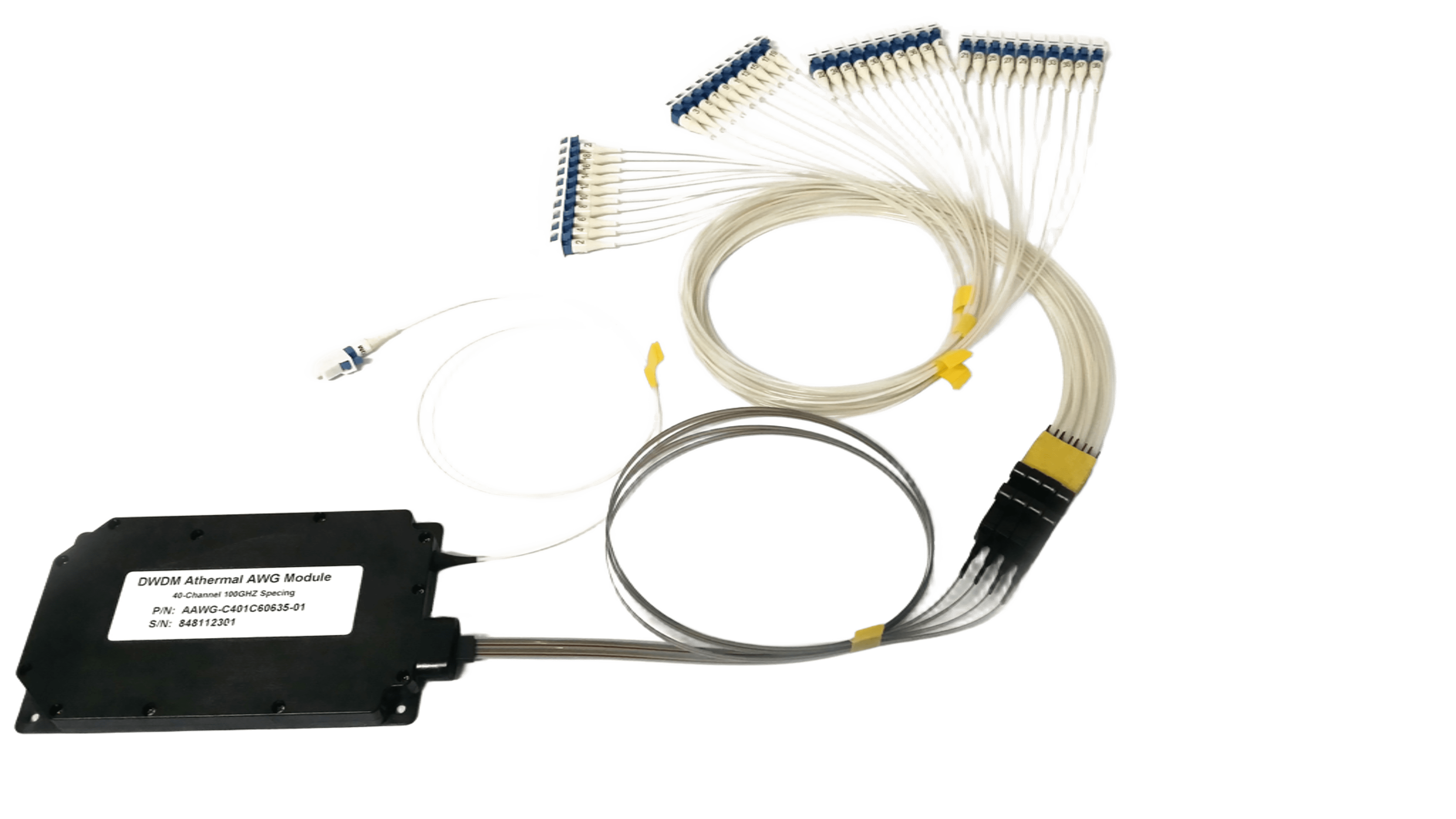
AWG
An Arrayed Waveguide Grating (AWG) is a planar optical device that functions as a wavelength multiplexer and demultiplexer in WDM systems. Unlike earlier thin-film filter (TFF)-based WDM modules, which use series-connected structures and suffer from accumulated power loss as channel counts increase—typically limiting them to no more than 16 channels—AWGs employ a parallel architecture that can multiplex and demultiplex dozens or even hundreds of wavelengths simultaneously.
This parallel processing capability makes AWG the preferred technology for modern DWDM systems, which typically transmit 40, 80, or even 96 wavelengths on a single fiber.
2.2 AWG Structure
A typical AWG consists of the following components:
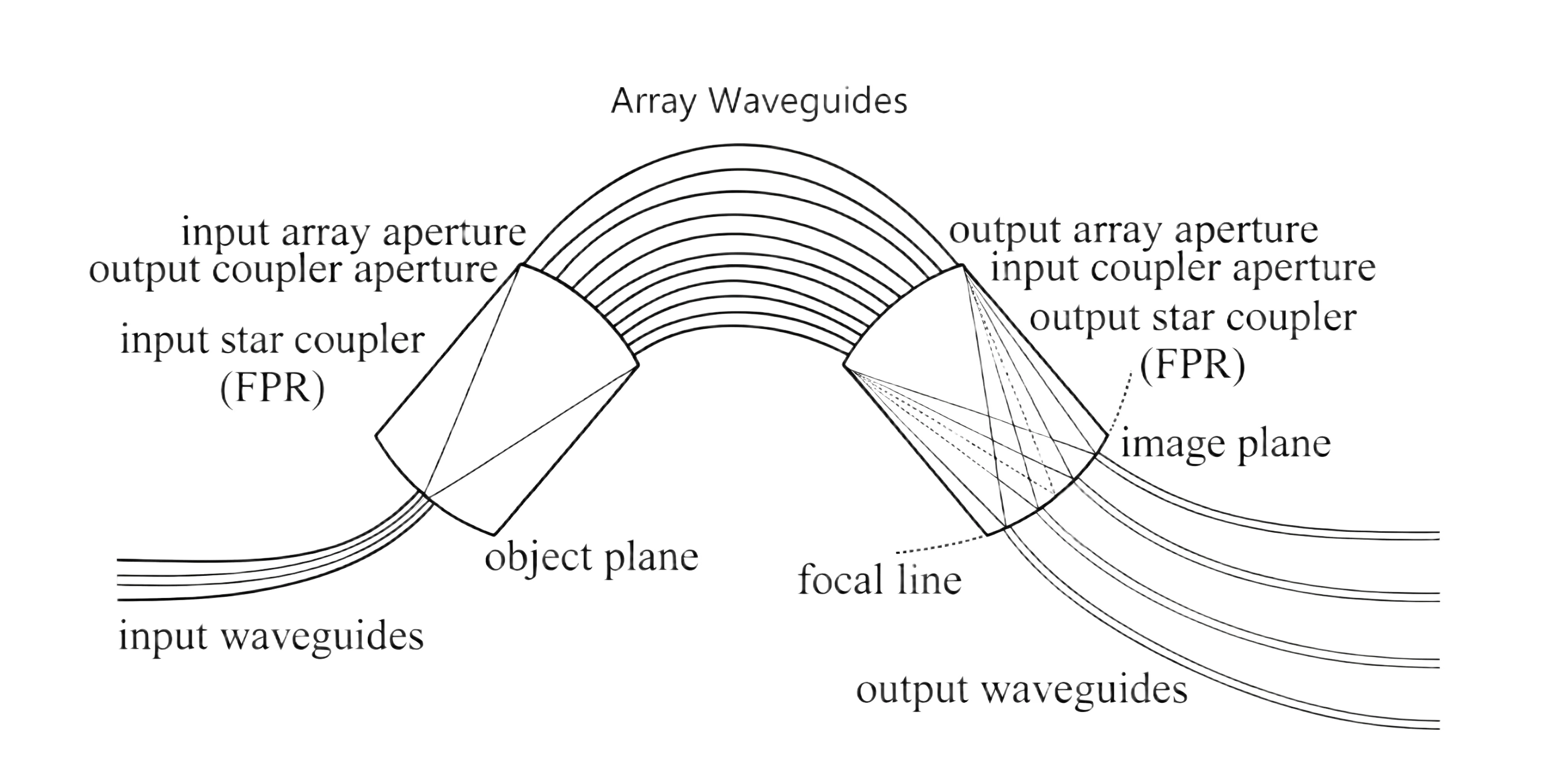
Input waveguide – carries the incoming DWDM signal
Input star coupler (free propagation region – FPR) – distributes the input light to the array waveguides
Array waveguides – a set of waveguides with arithmetically progressive length differences (ΔL) between adjacent channels
Output star coupler (FPR) – focuses and disperses the wavelengths
Output waveguides – receive the demultiplexed wavelength channels
All components are integrated on a single PLC substrate.
2.3 Working Principle
The working principle of an AWG can be understood by analogy with a concave diffraction grating.
Step 1: Light Distribution (Wavelength-Independent)
The DWDM signal enters through the input waveguide and propagates into the input star coupler. Through free propagation, the light is distributed equally to all array waveguides. This distribution process is wavelength-independent—all wavelengths are allocated to the array waveguides without discrimination.
Step 2: Phase Difference Generation
The array waveguides have progressively increasing lengths (constant path length difference ΔL between neighboring waveguides). As light travels through these waveguides, each path introduces a different phase shift. The phase differences between the multiple beams form an arithmetic progression, analogous to the behavior of a traditional diffraction grating.
Step 3: Wavelength Dispersion and Focusing
The phase-shifted beams exit the array waveguides and enter the output star coupler. Due to the phase differences, different wavelengths are dispersed and focused at different positions along the output star coupler's Rowland circle. This is the same principle as a concave grating: light emitted from one point on the Rowland circle, after diffraction, focuses at different points on the circle depending on wavelength.
Step 4: Wavelength Separation
The dispersed wavelengths are received by different output waveguides positioned at their respective focal points, achieving parallel demultiplexing of the DWDM signal. For multiplexing, the process is reversed.
2.4 Key Advantages of AWG Technology
Compared to competing technologies like TFF and Fiber Bragg Gratings (FBG), AWG offers:
|
Feature |
AWG Advantage |
|
Channel Count |
Supports 40–96+ channels vs. ≤16 for TFF |
|
Integration |
High integration density on a single chip |
|
Insertion Loss |
Low and uniform across all channels |
|
Scalability |
Easy to scale to higher channel counts |
|
Manufacturing |
Suitable for mass production |
|
Reliability |
No moving parts, passive operation |
|
Cost |
Declining cost per channel with higher volume |
3. The Role of AWG in DWDM Systems
3.1 The Foundation of DWDM Networking
AWG is the core filtering technology that has enabled the evolution of DWDM systems over the past two decades. It connects and disconnects different wavelength channels to and from transmission fibers.
In a DWDM network, AWG devices serve as:
Multiplexers (MUX) – combining multiple wavelengths onto a single fiber
Demultiplexers (DEMUX) – separating wavelengths at the receiving end
Optical Add-Drop Multiplexers (OADM) – selectively adding or dropping specific wavelength channels
3.2 Overcoming TFF Limitations
Early DWDM systems relied on TFF-based modules with series-connected structures. As the number of channels increased, these modules suffered from:
Uneven power loss – different wavelengths experienced different loss levels
Accumulated insertion loss – the last port faced the maximum loss
Channel count limitations – typically capped at 16 channels
AWG solves these problems with its parallel architecture, enabling simultaneous multiplexing/demultiplexing of 40, 80, or even 96 channels with uniform, low insertion loss across all ports.
3.3 Wavelength Routing and Channel Management
AWG is also used as a wavelength router in DWDM networks. By leveraging the wavelength-selective routing properties of the AWG, network operators can:
Route different wavelengths to different destinations without O-E-O conversion
Build highly efficient star metro WDM networks through extensive spatial wavelength reuse
Implement flexible channel management in transparent optical networks
4. The Role of AWG in Metropolitan Area Networks (MANs)
4.1 The Metro Gap Challenge
Metropolitan Area Networks operate on a scale between local area networks (LANs) and wide area networks (WANs). Traditionally, MANs have relied on SONET/SDH ring architectures, but electrical switching nodes are becoming bottlenecks for rapidly increasing traffic demands.
MANs are also much more cost-sensitive than WANs, requiring cost-effective solutions that can scale with demand.
4.2 AWG-Based Metro WDM Networks
AWG technology addresses these challenges by enabling cost-effective, scalable WDM networks for the metro environment. AWG-based architectures for MANs include:
Single-hop WDM networks – where all communication occurs in a single optical hop through the AWG, eliminating the need for intermediate O-E-O conversions
Star metro WDM networks – using the AWG as a central wavelength router, enabling efficient spatial wavelength reuse and reducing the number of required transceivers
4.3 Cost-Effectiveness and Scalability
Research has shown that:
AWG-CCA networks have the lowest cost for large-scale MANs
AWG networks have the lowest cost for small-scale MANs
AWG-based metro networks provide a practical path to:
Support GE/10GE/40GE/100GE service access
Conserve fiber resources by maximizing per-fiber capacity
Evolve to support 8, 16, 24, 40, 96, or 120 wavelengths
4.4 5G Front-Haul Applications
AWG technology is also finding increasing application in 5G front-haul networks. According to NGOF's "5G Front-Haul Technology and Application White Paper," the adoption of WDM solutions in front-haul is expected to increase from 1% in the 4G era to 15–17% in the 5G era. China Telecom has already initiated large-scale procurement of passive WDM color optical equipment for 5G front-haul.
5. The Role of AWG in Data Center Interconnect (DCI)
5.1 The DCI Bandwidth Explosion
Data Center Interconnect (DCI) is one of the fastest-growing segments in optical communications. The surge in AI computing, distributed cloud services, and low-latency applications has created unprecedented demand for high-bandwidth, low-latency interconnections between data centers.
5.2 AWG: The Ideal DCI Multiplexing Technology
Compared to Wavelength Selective Switches (WSS), AWG offers:
|
Feature |
AWG |
WSS |
|
Cost |
Lower |
Higher |
|
Channel Count |
Higher (80–96+) |
Lower |
|
Application |
Point-to-point high-capacity systems |
Flexible grid switching |
5.3 AWG Chips for Data Centers
AWG chips for data centers are core passive components for optical communications based on PLC technology. They are:
Key components for high-speed interconnects within data centers and DCI
Directly supporting the high-bandwidth, low-latency demands of cloud computing and big data applications
5.4 Market Growth and Trends
The AWG chip market for data centers is experiencing rapid growth:
Projected to grow from US$450 million in 2025 to US$811 million by 2032
Industry average gross profit margin has reached 45%
Key trends include:
Migration to higher-speed optical links (400G → 800G → 1.6T)
Increasing penetration of AWG solutions due to low cost, small form factor, and high integration
AWG chips and components for 1.6T optical modules already in small-volume production
6. HC Optical AWG Products
HC Optical offers a comprehensive range of AWG products designed for high-density DWDM applications.
6.1 50GHz 80-Channel Athermal AWG Module
The 80-channel 50GHz Athermal AWG is a high-density DWDM MUX/DEMUX solution available in 1U rackmount form factor. Key features include:
Athermal design – no external power or active temperature control required
80 channels across the C-band per ITU-T grid
High channel isolation – non-adjacent channel isolation ≥40dB
Low PDL – ≤0.50dB
Wide operating temperature – -40°C to 85°C
Flexible packaging – supports Corning SMF-28e+ fiber or custom options
6.2 Key Specifications
The product parameters listed here are for reference. For detailed specifications, please refer to the product page.
|
Parameter |
Specification |
|
Channel Spacing |
50GHz |
|
Number of Channels |
80 (or 96 customizable) |
|
Channel Isolation (Non-Adjacent) |
≥40dB |
|
PDL |
≤0.50dB |
|
Operating Temperature |
-40°C to 85°C |
|
Package |
1U Rackmount (150×70×12mm or custom) |
|
Fiber Type |
Corning SMF-28e+ or custom |
6.3 Applications
HC Optical's AWG products are suitable for:
1.DWDM system multiplexing and demultiplexing
2.Metro WDM networks
3.Data center interconnects (DCI)
4.5G front-haul and backhaul networks
5.Fiber optic amplifier systems
6.CATV fiber optic systems
7. Conclusion
Arrayed Waveguide Grating (AWG) technology has transformed optical networking by enabling the scalable, cost-effective multiplexing and demultiplexing of dozens of wavelengths on a single fiber. From its fundamental role as the core filtering technology in DWDM systems, AWG has become indispensable across:
DWDM networks – enabling 40–96+ channel transmission with low, uniform insertion loss
Metropolitan Area Networks – providing cost-effective WDM solutions for the cost-sensitive metro environment
Data Center Interconnects – serving as the ideal multiplexing technology for point-to-point high-capacity DCI systems
The global AWG chip market for data centers is projected to reach US$811 million by 2032, driven by the relentless growth in AI computing, cloud services, and 5G deployment. As optical networks continue to evolve toward higher speeds (400G, 800G, 1.6T) and higher density, AWG technology will remain at the forefront of optical innovation.
HC Optical's 50GHz 80-channel athermal AWG modules—with their high channel count, low insertion loss, excellent thermal stability, and flexible packaging options—provide network operators and system integrators with a reliable, future-ready foundation for next-generation optical networks.
This article is compiled based on our product materials and publicly available industry data. For more product information or custom solutions, please visit the HC Optical official website or contact the sales team.https://www.glhclink.com/contact us
Related news
- Optical Line Protection (OLP): Features, Applications, and Working Principle
- MEMS Optical Circuit Switch Selection Guide: How to Choose the Right Rackmount OCS
- Optical Amplifiers: The Engine Behind Modern Fiber Optic Networks
- Single Mode vs Multimode Fiber: Key Differences and How to Choose
- Optical Switch Comparison: MEMS vs Magneto-Optic vs Mechanical vs OCS
- Comprehensive Guide to Optical Isolators: Types, Working Principles, and Applications
- Comprehensive Guide to WDM Technology: Products, Applications, and Solutions
- How to Choose a Photodetector for Optical Communication Systems
- Photodetector Module Guide: Types, Applications, Specifications and Selection Tips
- The Essential Role of Optical Switches in Modern Test and Measurement Applications
