
Phase Modulator: A Complete Guide to Electro-Optic Phase Modulators for Coherent Systems
Updated at Oct 19th 2026 Views 7
Introduction
An electro-optic phase modulator is a key building block in modern photonic systems because it changes the phase of light without directly modulating its intensity. This capability is essential in coherent optical communication, interferometric fiber sensing, analog photonic links, and photonic quantum information processing.
Among the available material platforms, lithium niobate (LiNbO₃) remains a reference technology for high-speed, low-loss phase modulation. The HC-QN series from GLHC is a practical implementation of this platform, covering operating wavelengths from 770 nm to 1550 nm, modulation bandwidths up to 18 GHz, and half-wave voltages as low as 4 V.
This article provides a complete overview of lithium niobate phase modulators, including their working principle, key performance specifications, main applications, selection criteria, and why lithium niobate remains a preferred platform for demanding phase-control applications.
What Is a Phase Modulator?
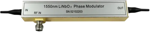
HC Phase Modulator
A phase modulator changes the optical phase of a light wave in response to an electrical drive signal while leaving the optical amplitude essentially unchanged. This distinguishes it from an intensity modulator, such as a Mach–Zehnder modulator, which converts phase shifts into amplitude changes through optical interference.
This difference is important in real systems. In a coherent optical link, information can be encoded in the phase of the optical carrier. A phase modulator imposes phase encoding directly, with a fast and largely linear electro-optic response. In an interferometric fiber sensor, phase modulation provides the carrier signal needed for homodyne or heterodyne demodulation, enabling recovery of small optical path-length changes caused by acoustic, strain, or temperature variations.
In short, when a system needs to control optical phase rather than switch optical power, a phase modulator is the appropriate component. Lithium niobate phase modulators are particularly attractive because they combine high speed, low insertion loss, good linearity, and high optical power handling.
View HC Phase Modulator.
How a Lithium Niobate Electro-Optic Phase Modulator Works
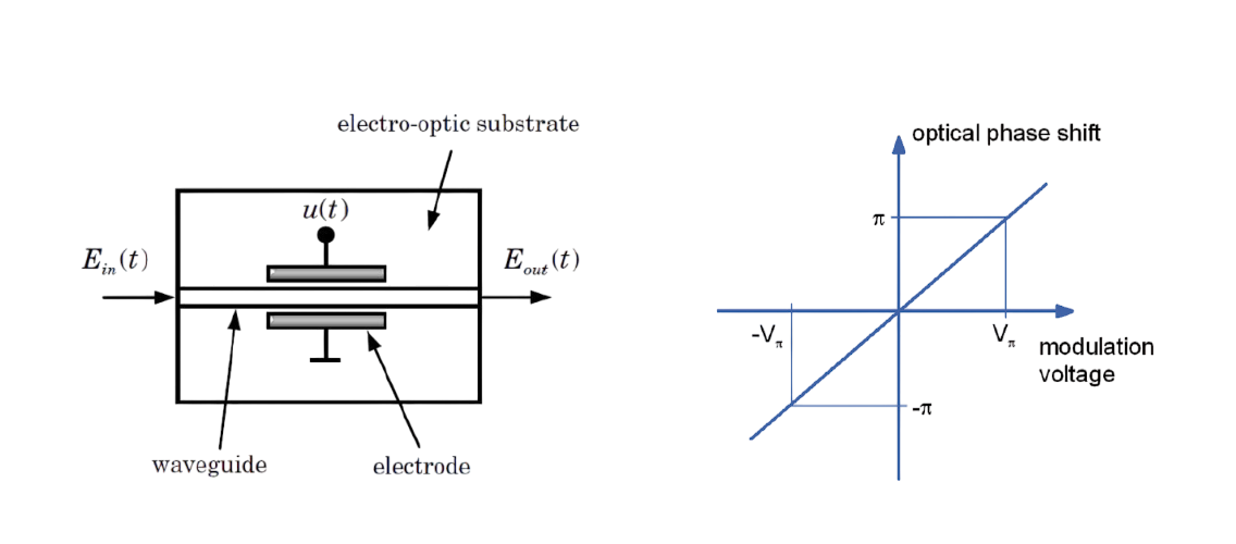
The HC-QN series uses the electro-optic effect of lithium niobate. When an electric field is applied to the crystal, the refractive index of the material changes, which shifts the phase of light propagating through an optical waveguide fabricated in the lithium niobate substrate.
The waveguide is typically produced using titanium diffusion or proton exchange, two well-established fabrication methods that provide low-loss and stable channel waveguides. These waveguides can support single-polarization or dual-polarization operation depending on the device design.
Because the phase shift is proportional to the product of the applied voltage and the interaction length, lithium niobate modulators can achieve a useful Vπ—the voltage required for a π phase shift—within a compact package. The electro-optic effect in LiNbO₃ is also very fast and largely linear, which is why lithium niobate modulators are widely used in applications requiring multi-gigahertz modulation bandwidth.
A practical advantage of a phase modulator is that it does not require a bias point in the same way as an interferometric intensity modulator. There is no transfer-function null that can drift, which simplifies bias-control circuitry and improves long-term stability in field-deployed systems.
Key Specifications That Determine Real-World Performance
Datasheet specifications are meaningful only when they are evaluated against system requirements. The following parameters are especially important when selecting a fiber optic phase modulator.
Half-Wave Voltage (Vπ)
Vπ is the voltage required to produce a phase shift of π radians. Lower Vπ is generally better because it reduces the drive power required from the RF amplifier and eases thermal management.
The HC-QN series offers Vπ values from 4 V to 5 V at 50 kHz across its wavelength variants. A low Vpi phase modulator is especially valuable in analog photonic links, where every decibel of RF loss affects link gain. It is also useful in quantum photonics experiments, where drive electronics may operate under low-noise or cryogenic conditions and excessive voltage swing is undesirable.
Modulation Bandwidth
Operating bandwidth determines the maximum symbol rate or RF frequency that the modulator can handle. The HC-QN family provides several bandwidth options: 300 MHz for lower-speed sensing and control loops, 10 GHz for mainstream coherent communication, and an 18 GHz variant for high-bandwidth analog or research applications.
Rise times follow accordingly: approximately 35 ps for 10 GHz-class devices and 18 ps for the 18 GHz model. Bandwidth is not a “more is always better” parameter. A narrower-bandwidth device may offer lower drive-voltage requirements and simpler impedance matching, so the modulator should be matched to the actual signal spectrum.
Insertion Loss and Optical Return Loss
Insertion loss (IL) directly affects the optical link budget. The HC-QN series achieves IL below 4 dB in the 1064 nm and 1550 nm variants, and below 5 dB in the 770–880 nm variant.
Optical return loss (ORL) of −40 to −45 dB indicates well-controlled back-reflections. This is important in sensitive interferometric systems where stray reflections can cause parasitic interference or destabilize a laser source.
Optical Power Handling
Maximum input optical power is another important specification. The HC-QN modulators are rated for 100 mW in most variants, with the 770–880 nm model rated at 20 mW.
High optical power handling is a significant advantage of lithium niobate compared with some other photonic platforms. In SBS suppression applications, where a phase modulator broadens the optical spectrum to raise the stimulated Brillouin scattering threshold in a high-power analog link, the modulator must handle the optical power it is helping to manage. A high optical damage threshold is therefore a functional requirement, not merely a convenience.
Main Applications of Electro-Optic Phase Modulators
Coherent Optical Communication
In a coherent transceiver, phase modulation is used to write phase-encoded symbols onto the optical carrier. The HC-QN series is designed for phase delay in coherent communication systems and optical chirp control in high-speed links.
The combination of low Vπ, multi-gigahertz bandwidth, and stable lithium niobate electro-optic performance makes these devices suitable for PSK and QPSK formats. A phase modulator may serve as the sole encoding element or as part of an IQ modulation stage.
Fiber-Optic Sensing and SBS Suppression
Interferometric fiber sensing systems—including fiber-optic gyroscopes, hydrophones, and distributed acoustic sensing architectures—rely on phase modulation to generate carrier signals for PGC demodulation and to suppress stimulated Brillouin scattering in long fiber spans.
A phase modulator for SBS suppression broadens the launched optical spectrum through phase modulation, raising the SBS threshold without introducing residual amplitude modulation that could corrupt sensitive phase measurements. The low insertion loss and high optical power handling of the HC-QN series are well aligned with this use case.
Quantum Communication and Quantum Optics
Phase modulators are widely used in quantum key distribution (QKD) and photonic quantum information experiments. In discrete-variable QKD, a phase modulator can encode basis and key information onto weak coherent pulses. In continuous-variable QKD, it may form part of the modulation chain alongside an amplitude modulator or an IQ modulator.
The HC-QN series lists phase modulation in quantum communication as a core application, reflecting the demand for low-Vπ, low-loss devices that preserve quantum state fidelity during modulation.
Analog Photonic Links and Optical Sideband Generation
In analog fiber links, phase modulation is used for optical sideband generation and for linearization of the modulation transfer function. The low half-wave voltage of lithium niobate phase modulators reduces the RF drive power needed to achieve a given modulation depth, which can improve link gain and noise figure.
The same characteristic makes these modulators attractive for laser coherent beam combining, where precise phase control across multiple amplifier channels is required.
How to Select the Right Phase Modulator: A Practical Checklist
Choosing a phase modulator requires matching device performance to system constraints. The following checklist reflects a practical selection process.
1.Define the operating wavelength first.Phase modulators are wavelength-specific because both the waveguide design and electro-optic response are optimized for a target band. The HC-QN series covers 770–880 nm, 1064 ± 60 nm, and 1550 ± 100 nm, spanning quantum sensing and atomic physics wavelengths, Nd:YAG-compatible bands, and the standard telecom C-band.
2. Match bandwidth to the signal.A 300 MHz modulator is sufficient for many fiber sensing and slow control loops. A 10 GHz device covers mainstream coherent data rates. An 18 GHz device serves high-speed analog and research applications. Selecting bandwidth far above the signal spectrum can add unnecessary RF design complexity.
3. Check Vπ against available drive electronics.A 4 V Vπ device relaxes the output swing requirement of the RF driver. If the system uses low-noise or cryogenic electronics, the lower Vπ option may be an enabling factor rather than a convenience.
4. Verify optical power handling against the link budget.
In SBS-suppression or high-power analog links, the maximum input optical power rating must exceed the actual launch power with sufficient margin. The 100 mW rating of the HC-QN series provides useful headroom for many high-power sensing and analog applications.
5. Confirm polarization and connector requirements.
The HC-QN modulators use polarization-maintaining Panda fiber with slow-axis alignment and are available with FC/APC or customer-specified connectors. Polarization alignment should be confirmed early because a misaligned PM fiber interface can reduce the polarization extinction ratio that the modulator is designed to preserve.
Why Lithium Niobate Remains a Reference Platform
Silicon photonics has advanced rapidly, but the free-carrier dispersion mechanism used in most silicon modulators does not offer the same fast, linear electro-optic response as lithium niobate. Silicon modulators also face optical power limits from two-photon absorption, whereas LiNbO₃ can handle the 100 mW-class power levels often required by analog and sensing links.
Thin-film lithium niobate is further improving bandwidth and voltage performance, with demonstrated devices exceeding 100 GHz. However, bulk and diffused lithium niobate phase modulators remain a proven, field-deployable choice for systems that prioritize low insertion loss, low Vπ, high optical power handling, and multi-wavelength availability.
The HC-QN series represents this mature platform: insertion loss below 4–5 dB, Vπ of 4–5 V, bandwidth options from 300 MHz to 18 GHz, and 100 mW optical power handling across three wavelength bands. For engineers building coherent links, interferometric sensors, or quantum photonic systems, it provides a phase modulation building block that allows the rest of the system—rather than the modulator—to set the performance ceiling.
Conclusion
A lithium niobate phase modulator is a critical enabling component for systems that require precise, high-speed optical phase control. Its fast electro-optic response, low insertion loss, low half-wave voltage, and high optical power handling make it suitable for coherent optical communication, fiber-optic sensing, SBS suppression, analog photonic links, and quantum photonics.
When selecting a fiber optic phase modulator, engineers should evaluate wavelength compatibility, modulation bandwidth, Vπ, insertion loss, optical return loss, maximum input optical power, polarization alignment, and connector requirements. The HC-QN series addresses these requirements with multiple wavelength options, bandwidths from 300 MHz to 18 GHz, Vπ values of 4–5 V, insertion loss below 4–5 dB, and optical power handling up to 100 mW in most variants.
In summary, lithium niobate electro-optic phase modulators remain a proven and versatile choice for demanding phase-control applications. By matching device specifications to system requirements, designers can achieve reliable performance in coherent communication, advanced fiber sensing, and quantum photonic systems without making the modulator the limiting factor in the optical link.
Contact our team to know more information.
Related news
- Intensity Modulator Guide: LiNbO₃, TFLN, Specs & Applications
- Optical Switches in High-Speed Optical Module Test Platforms: A Research Report
- Optical Line Protection (OLP): Features, Applications, and Working Principle
- MEMS Optical Circuit Switch Selection Guide: How to Choose the Right Rackmount OCS
- Optical Amplifiers: The Engine Behind Modern Fiber Optic Networks
- Single Mode vs Multimode Fiber: Key Differences and How to Choose
- Optical Switch Comparison: MEMS vs Magneto-Optic vs Mechanical vs OCS
- Comprehensive Guide to Optical Isolators: Types, Working Principles, and Applications
- Comprehensive Guide to WDM Technology: Products, Applications, and Solutions
- How to Choose a Photodetector for Optical Communication Systems
