
The Lithium Niobate IQ Modulator: for High-Order Coherent Optical Transmission
Updated at Oct 26th 2026 Views 9
In coherent optical systems, the ability to map complex electrical signals onto an optical carrier with high spectral efficiency is the foundation of modern high-capacity transmission. The lithium niobate (LiNbO₃) IQ modulator addresses this requirement directly, combining a nested Mach-Zehnder super-structure with titanium-indiffused waveguides on X-cut lithium niobate to deliver stable, wideband IQ modulation across the C-band.
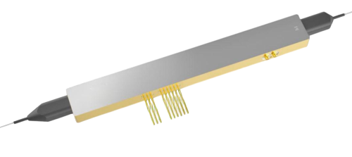 HC-IQ Modulator
How It Works: The DP-MZM Architecture
The device is built around a dual-parallel Mach-Zehnder modulator (DP-MZM) topology. Two independent Mach-Zehnder modulators are embedded in parallel within a larger Mach-Zehnder super-structure. Each internal MZM operates in a push-pull configuration and is designed for an electro-optic bandwidth above 20 GHz.
The modulation mechanism relies on the Pockels effect in lithium niobate. When an electric field is applied across the waveguide, the refractive index of the LiNbO₃ material changes, inducing a phase shift in the guided optical wave. In a Mach-Zehnder interferometer, this phase shift is converted into amplitude modulation through interference. To achieve IQ modulation, a π/2 phase offset is introduced between the outputs of the two parallel MZ modulators—this is accomplished by nesting them within the outer MZ super-structure. The result is independent control over the in-phase (I) and quadrature (Q) components of the optical field, enabling the generation of complex modulation formats.
A key operational enabler is the integrated monitor photodiode, which provides a feedback signal for automatic bias control (ABC). This stabilizes the modulator against thermal drift and bias-point wander, a critical requirement for maintaining constellation quality in coherent links.
Key Features
Titanium-indiffused waveguide on X-cut LiNbO₃: A mature, reliable material platform known for low optical loss and stable electro-optic performance.
Nested Mach-Zehnder (DP-MZM) structure: Enables true IQ modulation with independent I and Q drive ports.
>20 GHz electro-optic bandwidth per MZM: Supports high symbol-rate signaling and wideband analog modulation.
Integrated monitor photodiode: Facilitates automatic bias control for long-term operating stability.
Extended operating temperature range (–55 °C to +85 °C): Suitable for deployment in uncontrolled environments and harsh-condition applications.
C-band operation (1525–1570 nm): Compatible with standard erbium-doped fiber amplifier (EDFA) amplification windows and commercial C-band lasers.
Technical Specifications
The following parameters are representative for the LiNbO₃ IQ modulator. Unless noted otherwise, specifications are referenced at 25 °C and 1550 nm.
Optical Parameters
|
Parameter |
Symbol |
Min |
Typ |
Max |
Unit |
|
Operating wavelength |
λ |
1525 |
— |
1570 |
nm |
|
Insertion loss |
IL |
— |
5.0 |
7.0 |
dB |
|
Phase-MZ extinction ratio (@ DC) |
ERP |
— |
24 |
— |
dB |
|
Inner-MZ extinction ratio (@ DC) |
ERI |
24 |
29 |
— |
dB |
|
Polarization extinction ratio |
PER |
— |
20 |
— |
dB |
|
Optical return loss |
RL |
— |
40 |
— |
dB |
Note: An additional loss of up to 0.3 dB per FC/APC connector should be considered.
Electrical (RF) Parameters
|
Parameter |
Symbol |
Min |
Typ |
Max |
Unit |
|
RF Vπ voltage (@ 1 kHz) |
Vπ_RF |
— |
5.0 |
— |
V |
|
3 dB electro-optic bandwidth |
S21 |
20 |
23 |
— |
GHz |
|
S21 ripple (300 MHz – 20 GHz) |
ΔS21 |
–1 |
— |
1 |
dB |
|
Amplitude difference between inner MZs |
— |
–1 |
— |
1 |
dB |
|
Skew between inner MZs |
— |
–5 |
— |
5 |
ps |
|
Electrical return loss (40 MHz – 17 GHz) |
S11 |
–12 |
–10 |
— |
dB |
Bias Port Parameters
|
Parameter |
Condition |
Min |
Typ |
Max |
Unit |
|
Phase-MZ bias Vπ |
@ 1 kHz |
— |
7 |
8 |
V |
|
Inner-MZ bias Vπ |
@ 1 kHz |
— |
7 |
8 |
V |
|
Bias Vπ variation over wavelength |
wrt 1550 nm |
–5 |
— |
5 |
% |
|
Bias port impedance |
@ DC |
— |
1 |
— |
MΩ |
Monitor Photodiode Parameters
|
Parameter |
Min |
Typ |
Max |
Unit |
|
Reverse current |
— |
— |
2 |
mA |
|
Forward current |
— |
— |
10 |
mA |
|
Reverse voltage |
— |
— |
15 |
V |
|
Responsivity |
20 |
— |
120 |
mA/W |
|
Linearity |
–10 |
— |
10 |
% |
|
Phase error |
–5 |
— |
5 |
Degree |
Absolute Maximum Ratings
|
Parameter |
Min |
Max |
Unit |
|
RF input power |
— |
25 |
dBm |
|
Optical input power |
— |
25 |
dBm |
|
Bias voltage |
–40 |
40 |
V |
|
Operating temperature |
–55 |
85 |
°C |
|
Storage temperature |
–55 |
85 |
°C |
|
Operating humidity |
5 |
85 |
% |
To know more information about HC IQ Modulator please visit Lithium Niobate IQ Modulator-光通信方案提供商-恒创科技
Applications
The combination of >20 GHz bandwidth per MZM, stable bias control, and C-band compatibility makes this IQ modulator suitable for a range of advanced optical and RF-photonic use cases.
OFDM, QPSK, and QAM Modulation. The DP-MZM architecture supports high-order quadrature amplitude modulation and orthogonal frequency-division multiplexing, which are core formats in coherent optical transport, data-center interconnect, and high-capacity metro/long-haul systems. Independent I/Q drive ports allow the modulator to encode multi-level constellations with high spectral efficiency.
Carrier-Suppressed Single-Sideband (CS-SSB) Modulation. In analog photonic links and RF-over-fiber systems, CS-SSB reduces sensitivity to fiber dispersion and improves spectral occupancy. The nested MZ structure, combined with precise bias control, enables the necessary phase relationship between the I and Q paths to suppress the carrier and one sideband.
FMCW LiDAR for Autonomous Driving. Frequency-modulated continuous-wave (FMCW) LiDAR relies on coherent detection and chirped optical waveforms. The wide electro-optic bandwidth and stable bias operation of this modulator support the linear chirp generation required for high-resolution ranging and velocity measurement in automotive LiDAR systems.
FAQ
What is the difference between this device and a standard Mach-Zehnder modulator?
A standard MZM modulates only the amplitude (or phase) of light along a single path. This IQ modulator integrates two MZMs in parallel within an outer MZ super-structure, with a π/2 phase relationship between them. This allows independent control of the in-phase and quadrature components, enabling complex modulation formats such as QPSK and QAM.
Why is the integrated monitor photodiode important?
Lithium niobate modulators are susceptible to bias-point drift caused by temperature changes and charge accumulation. The monitor photodiode provides a real-time optical power feedback signal, which an automatic bias control (ABC) circuit uses to maintain the modulator at its optimal operating point, ensuring stable constellation quality over time and temperature.
For exact specifications, acceptance criteria, and customization options,please contact us via Contact Us-光通信方案提供商-恒创科技
Related news
- Phase Modulator: A Complete Guide to Electro-Optic Phase Modulators for Coherent Systems
- Intensity Modulator Guide: LiNbO₃, TFLN, Specs & Applications
- Optical Switches in High-Speed Optical Module Test Platforms: A Research Report
- Optical Line Protection (OLP): Features, Applications, and Working Principle
- MEMS Optical Circuit Switch Selection Guide: How to Choose the Right Rackmount OCS
- Optical Amplifiers: The Engine Behind Modern Fiber Optic Networks
- Single Mode vs Multimode Fiber: Key Differences and How to Choose
- Optical Switch Comparison: MEMS vs Magneto-Optic vs Mechanical vs OCS
- Comprehensive Guide to Optical Isolators: Types, Working Principles, and Applications
- Comprehensive Guide to WDM Technology: Products, Applications, and Solutions
