
Intensity Modulator Guide: LiNbO₃, TFLN, Specs & Applications
Updated at Oct 14th 2026 Views 2
1. What Is an Intensity Modulator?
An intensity modulator is an optical device that controls the optical power of a light beam by varying its transmission in response to an external control signal. The control signal is usually an electrical voltage, radio-frequency (RF) signal, or drive current, depending on the modulation technology used.
In optical communications, intensity modulation (IM) is a form of modulation in which the optical power output of a source is varied according to the modulating signal. The optical signal may travel as a free-space laser beam or propagate through an optical fiber or integrated waveguide.
The basic relationship is:
P_out(t) = T(t) × P_in(t)
where T(t) is the time-dependent transmission of the modulator. By changing T(t), the modulator changes the output optical power.
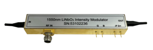 The picture of HC Optical LiNbO3 Intensity Modulator
2. Why Thin-Film Lithium Niobate (TFLN) Intensity Modulators?
Thin-film lithium niobate (TFLN) has emerged as a promising platform for next-generation intensity modulators. By confining light in a thin lithium niobate film, TFLN combines the strong electro-optic properties of lithium niobate with tighter optical confinement. This can enable compact Mach-Zehnder modulators with high bandwidth, low drive voltage, and good integration potential.
TFLN is especially attractive when system designers need:
1.Smaller device footprint
2.High-speed modulation
3.Lower drive voltage
4.Dense photonic integration
5.Strong electro-optic response
3. Key Specifications to Consider
When selecting an intensity modulator, evaluate these key parameters:
Modulation Bandwidth: How fast the modulator responds to the control signal.
Extinction Ratio (ER): The contrast between ON and OFF states. High ER is important for pulse generation and digital communication.
Insertion Loss (IL): Optical power loss introduced by the device.
Drive Voltage (Vπ): Voltage needed for a π phase shift; lower Vπ reduces driver requirements.
Operating Wavelength: The spectral range over which the modulator works.
Polarization Dependence: Some modulators require polarized input; others are polarization-independent.
Return Loss (RL): Indicates impedance matching in electrical and optical paths.
HC Optical LiNbO₃ Intensity Modulator Specifications
HC Optical offers LiNbO₃ intensity modulators for high-bandwidth analog applications. The LiNbO3 intensity modulator models combine high linearity with low drive voltage and small package size. Typical uses include optical communications, lidar, optical fiber sensing, and other fields.
Absolute Maximum Ratings
|
Parameter |
Condition |
Minimum |
Maximum |
Unit |
|
Maximum RF input power (electrical) |
RF port AC-coupled AC |
— |
25 |
dBm |
|
Maximum input optical power (optical) |
Continuous power CW |
— |
100 |
mW |
|
Enclosure operating temperature |
— |
0 |
+70 |
°C |
|
Storage temperature |
— |
−40 |
+85 |
°C |
|
Rate of change of maximum operating temperature |
— |
— |
1 |
°C/min |
|
Operating humidity |
— |
5 |
85 |
% |
|
Pin soldering temperature |
— |
— |
250 |
°C |
|
Maximum lead bonding time |
— |
— |
10 |
s |
Technical Specifications
|
Parameter |
Condition |
AM20 |
AM40 |
Unit |
|
Optical Parameters |
||||
|
Operating wavelength range |
— |
1525–1615 |
1525–1615 |
nm |
|
Insertion Loss, IL |
No connector |
< 4.5 (4.0 typical) |
< 5.0 (4.5 typical) |
dB |
|
With connector (3.5 typical) |
< 5.0 (4.0 typical) |
< 5.5 (—) |
dB |
|
|
Return Loss, RL |
No connector |
> 45 |
> 45 |
dB |
|
Extinction Ratio, ER |
— |
> 20 (23 typical) |
> 20 (23 typical) |
dB |
|
Electrical Parameters |
||||
|
S21 electro-optic bandwidth |
−3 dB |
> 20 (23 typical) |
> 30 (33 typical) |
GHz |
|
S11 return loss |
40 MHz–20 GHz |
< −10 (−12 typical) |
< −10 (−12 typical) |
dB |
|
20 GHz–35 GHz |
< −10 (−12 typical) |
< −8 (−10 typical) |
dB |
|
|
RF Vπ voltage @ 1 kHz |
— |
< 5.0 (4.5 typical) |
< 5.2 (4.7 typical) |
V |
|
RF Vπ voltage @ 20 GHz |
— |
6.0 |
6.0 |
V |
|
RF input impedance |
— |
50 |
50 |
Ω |
|
Bias Vπ voltage @ 1 kHz |
— |
< 5.5 (5.0 typical) |
< 5.5 (5.0 typical) |
V |
|
Bias input impedance @ DC |
— |
1 |
1 |
MΩ |
|
Photodiode responsivity |
— |
> 1×10⁻³ |
> 1×10⁻³ |
mA/W |
|
Linearity |
— |
±10% |
±10% |
— |
To Know more information and datasheet please visit LiNbO3 intensity modulator-光通信方案提供商-恒创科技.
Main Characteristics of HC Optical LiNbO₃ Intensity Modulators
Integrated polarizers
Integrated photodiodes
Low optical insertion loss
X-cut lithium niobate crystal
Titanium diffused waveguides
Operating bandwidths up to 60 GHz
Low drive voltage compatible with commercially available drivers
4. Applications of Intensity Modulators
Intensity modulators are essential in many photonic systems:
Optical Data Transmission: High-speed fiber-optic communication using formats such as Mach-Zehnder intensity modulator
Instrumentation: Precision optical power control for measurement and testing.
Analog Transmission: RF-over-fiber links for analog signal distribution.
Delayed Telemetry Systems: Timing and synchronization in distributed sensing networks.
High Frequency Fiber Connectivity: Microwave photonic systems requiring wideband modulation.
Lidar and Optical Fiber Sensing: Remote sensing and ranging.
Quantum Key Distribution (QKD): LiNbO₃-based Mach-Zehnder intensity modulators transmit different intensity pulses accurately.
Laser Material Processing: Power control for cutting, welding, and marking.
Laser Power Stabilization: Feedback control in precision experiments.
5. Why Choose HC Optical?
HC Optical’s LiNbO₃ intensity modulators are designed for demanding optical systems. With the AM20 and AM40 models, they support high-bandwidth analog applications with excellent linearity and low drive voltage.
Key reasons to choose HC Optical:
Proven LiNbO₃ platform: X-cut lithium niobate crystal and titanium-diffused waveguides.
Integrated functionality: Integrated polarizer and photodiode simplify system integration.
Low insertion loss: AM20: < 4.5 dB without connector; AM40: < 5.0 dB without connector.
High extinction ratio: > 20 dB, with 23 dB typical.
Low drive voltage: RF Vπ @ 1 kHz < 5.0 V for AM20 and < 5.2 V for AM40.
Wide operating wavelength: 1525–1615 nm.
Customizable options: Tailored solutions are available for specific application needs.
For high-bandwidth analog modulation, optical communications, lidar, fiber sensing, and QKD systems, HC Optical’s LiNbO₃ intensity modulators offer a reliable combination of performance, integration, and value.
FAQ
What is the difference between intensity modulation and phase modulation?
Intensity modulation varies optical power directly, while phase modulation varies the phase of the optical carrier. An intensity modulator can be made by combining a phase modulator with an interferometer.
Why is extinction ratio important?
Extinction ratio measures the contrast between ON and OFF states. A high ER is critical for optical pulse generation and digital communication. HC Optical modulators achieve > 20 dB, with 23 dB typical.
Are HC Optical modulators suitable for QKD?
Yes. LiNbO₃-based Mach-Zehnder intensity modulators are used in QKD systems to transmit different intensity pulses accurately.
Do HC Optical modulators support thin-film lithium niobate?
The AM20 and AM40 models use X-cut lithium niobate crystal and titanium-diffused waveguides. For TFLN-specific requirements.
If you are interested in intensity modulators or other optical communication equipment, please contact our expert team through Contact Us.
Related news
- Optical Switches in High-Speed Optical Module Test Platforms: A Research Report
- Optical Line Protection (OLP): Features, Applications, and Working Principle
- MEMS Optical Circuit Switch Selection Guide: How to Choose the Right Rackmount OCS
- Optical Amplifiers: The Engine Behind Modern Fiber Optic Networks
- Single Mode vs Multimode Fiber: Key Differences and How to Choose
- Optical Switch Comparison: MEMS vs Magneto-Optic vs Mechanical vs OCS
- Comprehensive Guide to Optical Isolators: Types, Working Principles, and Applications
- Comprehensive Guide to WDM Technology: Products, Applications, and Solutions
- How to Choose a Photodetector for Optical Communication Systems
- Why AWG Is the Preferred Choice for Next-Generation Optical Multiplexing
